
AI Data Center Out-of-Band Management: Where a Shielded Cat6A Patch Panel Fits
Share
AI Data Center Out-of-Band Management: Where a Shielded Cat6A Patch Panel Fits
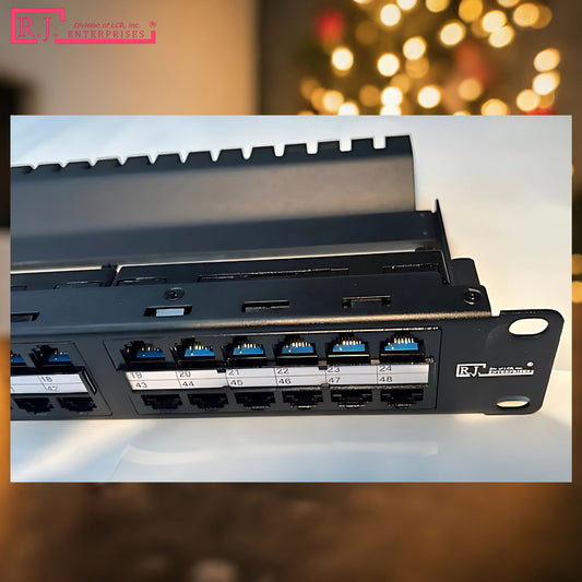
AI data-center racks are built around high-speed compute fabrics, but the fiber links that carry GPU workloads are only part of the operating picture. Every GPU server still needs a dependable management path for remote access, monitoring, power coordination, and recovery. That is where a structured copper layer—and a properly positioned RJ-HDPP-48S-C6A 48-port shielded Cat6A patch panel—can make rack operations easier to manage.
This article explains a practical rack-level role for the panel. It is not a substitute for a facility design, equipment documentation, or applicable codes and standards. Instead, it shows how a 48-port shielded Cat6A patch panel can aggregate the copper connections that support out-of-band (OOB) management while the high-bandwidth GPU network remains on its own fiber layer.
Compute traffic and management traffic have different jobs
In an AI rack, GPU servers, leaf/spine switches, and high-speed uplinks often rely on fiber interfaces such as LC or MPO/MTP. Those links handle the data paths associated with storage, training, inference, and east-west traffic. The NVIDIA InfiniBand overview is one example of the type of high-performance fabric used in accelerated computing environments.
Copper remains valuable because many supporting devices use RJ45 Ethernet rather than the main compute fabric. These commonly include baseboard management controller (BMC) ports, iDRAC, iLO, IPMI interfaces, management switches, console servers, monitoring appliances, intelligent PDUs, environmental sensors, and remote reboot controllers. Keeping these connections separate from the production fabric can simplify diagnosis when a server or its operating system is unavailable.
The NIST platform-firmware resiliency guidance provides useful context for why dependable administrative access and platform recovery matter. A patch panel cannot secure or replace a management architecture by itself, but it can give that architecture a clean, traceable physical layer.
Recommended rack placement: below the ToR, above the management switch
A practical location for the RJ-HDPP-48S-C6A is around U28, below the Top-of-Rack (ToR) switch and above the dedicated management/OOB switch. This placement makes the panel the visible boundary between the high-speed fiber network above and the lower-speed copper management network below.
| Rack position | Component | Connection layer | Primary role |
|---|---|---|---|
| U42–U40 | Fiber patch tray and leaf/spine jumpers | MPO/MTP or LC fiber | 100G/200G/400G compute-fabric paths |
| U38–U32 | GPU server nodes | Fiber compute; RJ45 management | GPU workloads plus BMC/IPMI access |
| U30 | Top-of-Rack switch | High-speed fiber uplinks | Compute-network aggregation |
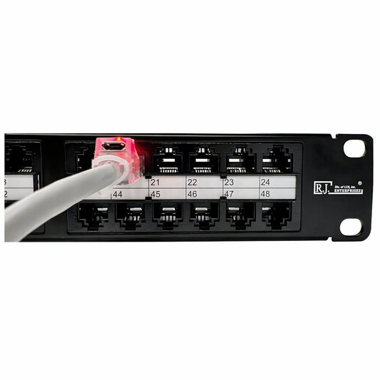
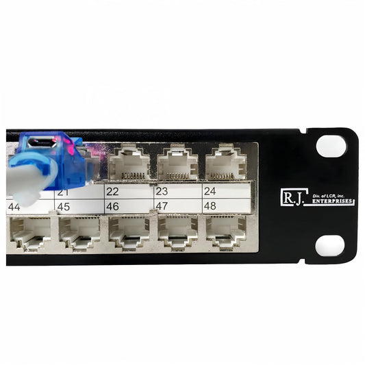
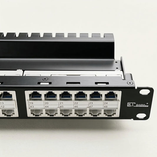
| U28 | RJ-HDPP-48S-C6A 48-port shielded Cat6A patch panel | Shielded Cat6A copper | Aggregates BMC/IPMI, OOB monitoring, remote reboot, and other management connections |
| U26 | Management / OOB switch | 1G/10G copper | Dedicated management-network connectivity |
| U24 | Intelligent PDU and power monitoring | Cat6/Cat6A copper | Power visibility and monitoring |
| U22 | Facility/security connections | Copper, when routed through rack | Approved camera, access-control, or HVAC interfaces |
Product advantage: The RJ-HDPP-48S-C6A is designed to reduce patch-panel rack space by 50% and installation time by up to 90%, compared with conventional patch-panel layouts.
With the panel at this handoff point, short horizontal runs from GPU-server management ports can terminate cleanly on the rear of the panel. Short, labeled patch cords can then connect its front ports to the OOB switch below. That makes adds, moves, tests, and troubleshooting less disruptive than tracing individual copper runs directly into switch ports.
For background on the hardware itself, see our guide to what patch panels do and our explanation of high-density patch panels.
What the RJ-HDPP-48S-C6A can aggregate
A 48-port panel gives the rack team an organized point for copper management connections. Port allocation should reflect the site’s labeling scheme and growth expectations, but a rack might reserve groups of ports for the following roles:
- GPU-server BMC ports: Dedicated Ethernet access to iDRAC, iLO, IPMI, or other vendor management controllers.
- OOB monitoring: Connections for console servers, network monitoring appliances, or telemetry collectors.
- Remote recovery: Remote reboot controllers or other support equipment used during recovery procedures.
- Power and environmental systems: Intelligent PDUs, rack sensors, or monitoring gateways that use Ethernet.
- Facility devices: Copper drops for approved security, HVAC, or access-control components when the facility design routes them through the rack.
The exact port count for each category depends on the rack design. The value of the panel is not that every one of its 48 ports must be populated on day one; it is that the physical layer can stay documented and expansion-ready instead of becoming a bundle of unmarked point-to-point patch cords.
Why shielded Cat6A is a sensible choice for this layer
Cat6A structured cabling is commonly specified where 10GBASE-T capability and a more future-ready copper infrastructure are desired. The Fluke Networks comparison of Cat6 and Cat6A is a helpful resource when evaluating the category decision. The patch-panel category should match the installed horizontal cable, compatible keystone modules, and the overall channel design.
Shielding can be useful in electrically busy environments, but it is not a standalone cure for interference. For a shielded system to perform as intended, the cable, jacks, patch panel, bonding, grounding, and installation practices must be considered together. The Fluke Networks shielded-cabling guidance discusses the importance of the complete shielded channel.
That is particularly relevant in dense AI environments that combine GPUs, power distribution, cooling equipment, and many parallel cable pathways. The RJ-HDPP-48S-C6A should be positioned as part of a coordinated shielded Cat6A system—not as a promise that it will solve every EMI, grounding, or performance issue by itself.
Labeling and testing turn a panel into an operational tool
In an OOB network, a clearly labeled port can save valuable time during an incident. Use a consistent naming convention that identifies the rack, equipment position, device role, and remote management interface. For example, a label such as R12-U34-GPU03-BMC tells a technician more than a generic port number. Mirror the same identifiers in the cable records and the management-switch configuration.
Test every permanent copper run before service. A wire-map test can identify common termination faults, while qualification or certification testing should be selected based on the installation scope and the applicable design requirements. Fluke’s wire-map testing overview explains why matching conductor colors alone is not enough. Our article on crosstalk also covers one reason disciplined termination and pathway practices matter.
How this fits with data-center cabling practice
The TIA-942 data-center telecommunications infrastructure standard is often referenced when organizations develop data-center cabling and infrastructure requirements. Your project team should confirm the standard edition, local requirements, and customer specifications that apply to the facility. A 48-port patch panel supports the broader goals of organized pathways, identifiable connections, and maintainable infrastructure, but the full standard covers far more than one rack component.
For an overview of the operational stakes in these environments, read our data-center efficiency article. For teams building out the copper layer, browse our patch-panel collection and the keystone-jack collection to match panel, jack, and cable category choices.
Build a clean OOB layer before it is urgently needed
When an AI server, operating system, or production network path is unavailable, the management network is often the route technicians rely on to investigate and recover. Placing the RJ-HDPP-48S-C6A between the fiber-heavy compute equipment and the OOB switch gives those copper paths a disciplined home: accessible, labeled, testable, and easier to scale.
In short, let fiber carry the AI compute fabric and let the shielded Cat6A patch panel organize the operational layer that helps keep the rack serviceable. Review the rack design with the network, facilities, and security teams, then select the patch-panel and keystone combination that matches the installed cabling system and planned management architecture.